HASTELLOY® C-22® alloy for Cryogenic Bellows in the Space Shuttle
Corrosion Evaluation of Alloys for Flexura Hosing in the Space Shuttle Launch Environment, By J.L.Nickerson and A.T.Asphahani
Abstract
Vacuum jacketed cryogenic supply lines at the space shuttle launch site were once made of 304L stainless steel. Due to the extremely corrosive conditions encountered at the launch site, the convoluted flexural hosing suffered severe pitting corrosion within a short time. The pitting led to perforation causing a loss of vacuum and resulting in a high boil-off of the cryogenics. In response to this situation, and extensive testing program was initiated to find a suitable alloy for the flex hose. Corrosion tests (including immersion testing, electrochemical studies, accelerated salt fog/acid dip testing, and beach exposure evaluations) were conducted on nineteen different alloys. HASTELLOY® C-22® alloy was identified as being the best of all alloys tested. The test results and the required mechanical properties, fabrication and ease of welding led to the selection and installation of the C-22® alloy bellows at the launch site. The basis for designing advance, corrosion-resistant C-type allots, along with data on pitting corrosion and corrosion fatigue performance of thin gauge sheet products are presented. In addition, information on stress corrosion cracking, hydrogen embrittlement, cavitation-erosion characteristics and corrosion resistance of weldments are provided. A brief description of successful industrial application of the C-22® allot is included.
Introduction
For years, nickel and nickel-base allots have been depended upon to handle highly corrosive chemicals and to provide a reliable approach to corrosion prevention and control. The Ni-Cr-Mo/W alloy system is very versatile in its resistance to a wide variety of aggressive conditions. This is due to the outstanding resistance of nickel to hot or cold alkalies1, an improved resistance oxidizing media when the chromium is added, and also the excellent resistance to reducing halide environments when nickel is alloyed with molybdenum and/or tungsten.
While some metals (e.g., Ta, Ti) and their alloys offer excellent resistance to several corrosive media, these materials fail to provide the versatility of the Ni-Cr-Mo/W system, especially when fluoride ions are present. Also, many of the refractory and reactive metals often do not permit practical fabrication of new components of reliable field repairs. In contrast, the Ni-Cr-Mo/W alloys have been well known for their excellent weldability which has increased their acceptance as the best, economical choice for solving severe/chronic corrosion problems.
Of the Ni-Cr-Mo/W system, alloy C has been a prominent alloy. The conception of this alloy dates back to the early nineteen-thirties2. Since then, many generations of the alloy C-type were developed, based on advances in process metallurgy and on better understanding of corrosion phenomena. This paper will describe the newest and the most advanced product of the alloy C-type; i.e., C-22® alloy. The basis for this alloy’s design, its improved corrosion and mechanical properties and its selection for the flexural bellows cryogenic fuel transfer lines on the space shuttle launch site will be discussed.
- Background – Basis for C-22® Alloy DesignDuring the early development if the C-type alloys, it was recognized that the relatively high carbon, silicon, and vanadium contents were tolerated at the expense of some corrosion resistance in order to facilitate production. The initial commercial grade of alloy C, which was a cast product, contained (in wt. %) 16.5-17.5 Mo, 13.5-15 Cr, 4.5-5 W, 5.5-6.5 Fe, 0.25-0.75 Mn, 0.25-0.75 Si, 0.20-0.35 V, 0.12 C maximum, and the balance nickel. The micro-constituents of alloy C were identified by Forging3 to be a nickel-rich fcc, solid solution with carbides of the form of M6C and Cr4C. With this identification, the minimum chromium content of the alloy was raised from 14.5 wt. % to 15.5-17.5 wt. % to suppress intergranular heat-affected-zone attack.Further development in melting and processing practices; e.g., oxygen blowing of heats, made it possible to reduce the carbon content of alloy C to a nominal 0.05 wt. %. With this development, it became feasible to have large-scale production of the wrought alloy. However, grain-boundary precipitation of carbides in the as-welded condition was known to promote intergranular corrosion. This required a post-weld solution heat treatment in order to dissolve the carbides and restore the corrosion resistance of the alloy.The important role played by the relatively high carbon and silicon contents led researches at BASF4 to develop alloy C-276 with 0.01 wt. % C maximum and 0.08 wt. % Si maximum. The advent of the argon-oxygen-decarburization (AOD) process made alloy C-276 a commercial reality.Despite its excellent corrosion resistance, alloy C-276 was not completely free of preferential weld and heat-affected zone attack due to precipitation of Mo and W rich intermetallic phases.5 The electron vacancy number (Nv) of alloy C-276 had not been controlled and, as a consequence, the alloy became susceptible to formation of intermetallic compounds of the mu-phase type when exposed to temperatures in the range of 650°C-1100°C.Formation of mu-phase also reduces the corrosion resistance of alloy C-type. The understanding of the concepts of electron concentration (electron vacancies) and their relation to the formation of intermetallic compounds, along with the computerized manipulations of chemical adjustments, led to the development of one of the most thermally stable Ni-Cr-Mo alloys; i.e., alloy C-4.6 This alloy, which contains no tungsten and has a reduced iron content does not precipitate mu-phase after exposure of up to 100 hours to temperature in the range of 650°C-1100°C. Also, the secondary carbide precipitation in alloy C-4 has been further reduced as a result of both improved melting control and titanium stabilization.
Even though alloys C-276 and C-4 possess versatile corrosion resistance, both alloys exhibit limited resistance to oxidizing acid environments. In addition, alloy C-276 has impaired thermal stability due to mu-phase precipitation. Alloy C-4 overcomes this problem, but its lack of tungsten results in reduced resistance to localized corrosion attack (e.g., pitting/crevice corrosion). Advances in corrosion science and better understanding of the specific roles of chromium, molybdenum and tungsten in imparting corrosion resistance to nickel-base alloys have led to a new generation of this versatile Ni-Cr-Mo/W family; i.e., C-22® alloy.7 The chemistries of C, C-276, C-4 and C-22® alloys are listed in the Table 1, along with all other alloy tested by NASA at the John F. Kennedy Space Center.
The criticality of the proper amounts of chromium, molybdenum, and tungsten in C-22® alloy is based on the fact that in reducing acids, molybdenum and tungsten are beneficial additions for uniforms and intergranular corrosion resistance. Molybdenum and tungsten, however, are ineffective additions for uniform corrosion resistance in oxidizing acid environments.8 The role of chromium is just the opposite of molybdenum and tungsten; that is chromium is ineffective in reducing acids and beneficial in oxidizing acids. In view of various compositions is an atomic percent factor (APF) that reflects the opposing role of chromium to that of molybdenum and tungsten. The atomic weights of the elements involved are chromium: 52, molybdenum: 96, and tungsten: 184. As such, tungsten is approximately twice as heavy as molybdenum and four times heavier than chromium. Therefore, the atomic percent factor is defined as the ratio of four times the chromium weight percent factor is defined as the ratio of four times the chromium weight percent over the sum of twice the molybdenum weight percent and once the tungsten weight percent (i.e., APF = 4Cr/[2Mo + 1W]).
In oxidizing environments, such as nitric acid and sulfuric acid plus ferric sulfate (ASTM G-28A), the higher the chromium content (the higher the atomic percent factor), the lower are the corrosion rates. On the other hand, in reducing environments such as boiling hydrochloric acid and dilute sulfuric acid, the higher the molybdenum and tungsten contents (the lower the atomic percent factor), the lower are the corrosion rates.
The ultimate versatility providing the best resistance to both oxidizing and reducing environments is achieved by the careful adjustment of alloying elements to yield an atomic percent factor in the range of 2.5 to 3.3 (Figure 1). C-22® alloy, with about 22 wt. % Cr, 13 wt. % Mo, and 3 wt. % W lies within this range identified for the lowers corrosion rates and oxidizing and reducing environments. (Note: 3 wt. % Fe is also an essential alloying factor for improving the processing characteristics of the Ni-Cr-Mo-W system).
In addition, such a composition of about 22Cr-13Mo-3W-3Fe in nickel-base alloys shows a much improved thermal stability over that of the 16Cr-16Mo-4W in alloy C-276. Intergranular corrosion is observed in alloy C-276 within less than two minutes of aging at 928°C, while C-22® alloy remains resistant to fifteen minutes (Figure 2).
Initially, it was thought that the improvements in uniform corrosion rates would be achieved at the expense of resistance to pitting and crevice corrosion. However, the resistance of such forms of localized attack was actually improved.9 C-22® alloy showed the best resistance to pitting and to crevice corrosion attack, as characterized by the critical temperatures above which pitting or crevice corrosion occur as shown in Table 2. The higher the temperature required to induce pitting or crevice corrosion in an alloy, the more resistant the alloy is to localized attack. Consequently, C-22® alloy showed the best performance of the alloys in the Ni-Cr-Mo/W family. It is presumed that in terms of localized corrosion, the increase in chromium content in C-22® alloy has more than compensated for the slight reductions in molybdenum and tungsten, as compared to those of alloy C-276.
- Corrosion Evaluation of Candidate Alloys for Flexural Hosing SelectionThe original alloy of construction for convoluted flexible hoses on the Orbiter launch site was 304L stainless steel. Due to the harsh salt air environment combined with hydrochloric acid products as a result of the fuel combustion reaction during lift off, the 304L cryogenic vacuum jacked lines failed by pitting corrosion. Small pinhole leaks in these transfer lines led to high boil-off of the cryogenics leading to loss of insulation. Therefore, it was NASA’s intent to find an alloy resistant to pitting corrosion in a high chloride environment as well as one with excellent mechanical and stress corrosion cracking properties due to the extensive forming encountered in the fabrication of flexible convoluted bellows.Electrochemical screening tests were performed on all 19 candidate alloys in 3.55 weight percent sodium chloride with 0.1 Normal hydrochloric acid to determine susceptibility to localized corrosion resistance. Details of the test procedure are described elsewhere.10As a result of the first round of testing, it was determined that the most resistant alloys to the test environment were HASTELLOY® C-22® alloy, C-276 and C-4, INCO® alloys 625 and G-3, and FERRALIUM® alloy 255, 7Mo + N, ES2205, and 904L stainless steel. Test results criteria for these selections included measurements of the corrosion potential (Ecorr), cyclic polarization values for the critical pitting potential (Ec), the protection potential (Ep) and area in the hysteresis loop coulombs, as well as weight loss and visual inspection after testing.Electrochemical testing was repeated on the nine most resistant alloys in a higher acid concentration of 3.55 percent NaCl with 1.0N HCl environment.Results of this testing are in Table 3. Values for 304L stainless tested in the lower acid concentration test environment are included for comparison.
Corrosion potential measurements were conducted. The data in Table 3 show there is a dramatic cut-off point in the corrosion potential values between the Ni-based alloys (C-22®, C-276, C-4, 625 and G-3) and the iron-based alloys.
Cyclic polarization test results are somewhat less dramatic. A noble critical pitting potential gives an indication of superior resistance to pitting corrosion, and it is desirable that the protection potential be higher than the critical pitting potential. Test results indicate that only 904L and ES2205 (along with 304L) are not ideally suited in this environment, since the protection potential (Ep) has more negative values than the corresponding critical pitting potential (Ec). Note that 304L had very low values for Ec and Ep even in the lower concentration acid solution.
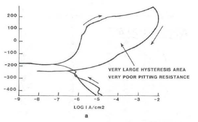
The hysteresis loop measured from the cyclic polarization curves and the tabulated data are given in Table 3. Essentially, the smaller the area measured inside the hysteresis loop in the passive range of curve, the more resistant an alloy is to localized corrosion. Typical cyclic polarization curves for resistant and non-resistant alloys are shown in Figure 3. The data show that the Ni-based alloys are more resistant than the Fe-based alloys. One exception was the duplex stainless steel, FERRALIUM alloy 255, which performed as well as alloys 625 and C-4.
Excellent correlation between the various electrochemical results combined with general corrosion weight-loss measurements show that the alloys which best resist the test environment are HASTELLOY® alloys C-22®, C-276, C-4 and INCO alloys G-3 and 625.
Salt fog chamber exposure as per ASTM B11711 at 35°C (95°F) for cyclic durations of 168 hours followed by a one-minute immersion dip in 1.0 Normal hydrochloric acid/0.3 micron alumina mixture (simulation of booster effluent created during launch) showed good correlation with the electro-chemical test results. Figure 4 shows weight loss of the 19 candidate alloys for a total test duration of 20 weeks. Again, the Ni-based alloys as well as Zirconium 702 were tested to be the most resistant alloys with HASTELLOY® C-22® alloy the best performer.
Cyclic beach corrosion exposure at the Kennedy Space Center Beach Corrosion Test Site followed by and HCl/alumina spray similar to the salt fog chamber/acid dip testing was performed on the 19 candidate alloys for up to 251 days with 13 acid sprays. Results of the testing are shown in Figure 5. These results are consistent with previous data showing the Ni-based alloys, with C-22® alloy at the top, outperforming all others tested. Similar results were also observed from evaluation in the ferric chloride immersion testing (Table 4).
As stated in the NASA report “In all the testing, by electrochemical methods, salt/fog acid dip, beach exposure/acid spray, and ferric chloride immersion, the same materials are at the top of the list. The HASTELLOY® C-22® alloy has displayed superior corrosion resistance during all the testing.”12 Bellows have been made of the C-22® alloy and were welded, on site, to the existing 304L stainless steel structure (see Appendix A).
- Thin-Gauge Sheet Properties and Corrosion CharacteristicsThe primary goal of the test program was to select an alloy of construction for the flexural bellows hosing to replace 304L stainless steel. The replacement alloy had to resist pitting corrosion in the salt air/hydrochloric acid environment. Since thin-gauge material (0.025” – 0.038” thick) is used in the construction of the bellows, it is of concern that minor pitting attack might lead to perforation. Also, due to the extensive forming involved in the construction of the convoluted hoses, considerations for resistance to stress corrosion cracking, corrosion fatigue and corrosion of weldments were also important. In addition, good mechanical properties and ease of fabrication/welding were other key factors in the selection of the replacement alloy.In order to distinguish the top performer in thing-gauge sheet, aggressive “critical pitting temperature” testing was performed in Green Death13 test solution (7 Vol. % H2SO4 + 3 Vol. % HCl + 1% FeCl3 + 1% CuCl2). The tests were conducted on 0.004”-thick sheet of alloys C-276 and C-22® (supplied by the same thin-gauge reroller). The critical pitting temperature for alloy C-276 was determined to be 120°C, after 24-hour exposure. The C-22® alloy did not pit at test temperatures up to 125°C in this aggressive oxidizing chloride-sulfuric acid environment. Figure 6 shows the pits in alloy C-275 foil after an additional exposure at 125°C whereas, the C-22® alloy foil, even with the additional exposure, continued to resist pitting. The data confirmed earlier reports on the better performance of the C-22® alloy, when compare to that of alloy C-276.14Cross-section micrographs of the tested foils (Figure 7) show alloy C-276 to be loaded with primary carbide precipitates throughout the foil while the C-22® alloy foil shows a clean microstructure. The primary carbide precipitation is probably the result of excessive cold forming in the reroll process combined with final anneal/heat treatment. It should be noted, however, that the C-22® alloy foil, processed by the same company under the same conditions, shows only slight precipitation in some of the grain boundaries (at 500× magnification). It is expected that not only will the corrosion properties of the alloy C-276 foil be effected negatively, but also the alloy in this condition may have compromised mechanical properties particularly in fabricated bellows. This is not the case for the C-22® alloy due to its ease of processing and to its inherently improved corrosion properties over that of the old alloy C-276.Good fatigue properties are an important factor for flexural bellows. Specialized testing of 0.004”, thing-gauge sheet (simulating air heaters/dampers-seal applications) has shown C-22® alloy to pass the required 10,000-cycle test. In addition, thermal-cycle/fatigue testing for dimensional stability (two minutes at 900°C followed by fifteen minutes at 200°C) showed the C-22® alloy to pass the 1,000-cycle test as 0.001” thick sheet with no cracking or changes in dimension.15Cyclic fatigue testing of longitudinally welded sample clamshell bellows with three convolutions each was performed on 304L, INCONEL 625 and HASTELLOY® C-22® alloy by NASA.16 A summary of the data is given in Table 5. During the mechanical cycling, the sample bellows were maintained under vacuum and pressure changes, due to crack initiation, were monitored with a vacuum thermocouple gauge. The data in Table 5 show that the fatigue life of the C-22® alloy bellows far exceeded that of 304L stainless steel and was better than that of INCONEL 625.
Standard U-bend, stress corrosion cracking with autogenous and composite welds at the center of the bend were also exposed to the salt fog chamber/acid dip, beach exposure/acid spray, and ferric chloride immersion test environments. After several months of exposure the only samples which stress cracked were 304L stainless steel welded with 304L (eight-week exposure) and FERRALIUM 255 alloy welded with FERRALIUM 255 alloy (12-week exposure).
More severe stress corrosion cracking tests of nickel-based alloys, in the aggressive sulfur-bearing sodium chloride environments14 show HASTELLOY® C-22® alloy to be the best performer (Table 6). Also, test in bromide solutions, in “acidizing” HCl environment, and in magnesium chloride solutions at elevated temperatures confirm the better performance of C-22® alloy over those of alloys C-276 and 625 (Tables 7A and 7B).
Hydrogen embrittlement caused by corrosion reactions that may generate cathodic hydrogen is also a concern particularly for thin-gauge material applications, such as the space shuttle fuel cell transfer line bellows. Standard stress cracking testing (as per NACE Standard MR0175-8417) using two-point bend tests 0.040-inch thick samples were conducted on HASTELLOY® alloys C-22® and C-276, galvanically coupled to carbon steel. Test results are given in Table 8. It ca be seen that while alloy C-276 cracked when 20% cold rolled, then aged at 500°C fir 100 hours or when 40% cold rolled, then aged at 204°C for 200 hours, the C-22® alloy did not crack even up to 40% cold-rolling plus aging treatment at the 204°C.
Cavitation-erosion test results for 316L stainless steel, Sadvik 2205, and HASELLOY® alloys G and C-22® are shown in Figure 8. The cavitation-erosion behavior of C-22® alloy is better than the other nickel-based alloy G and the duplex stainless steel 2205, and superior to that of 316L stainless steel. Based on these test data, it is expected that under fluid flow conditions the performance of C-22® alloy would be an improvement over other nickel-based alloys and stainless steels.
Dissimilar weld properties were another key factor in the selection of a replacement alloy since the flexural hosing would be welded into the existing 304L stainless steel piping system. Laboratory corrosion testing was performed on several base metals (317L, 904L and alloy G-3) joined by gas tungsten arc welds. Similar weld filler metals, HAYNES® alloy No. 625 and HASTELLOY® C-22® alloy dissimilar filler metals were used. Weld metal critical pitting temperature in ferric chloride and Yellow Death (4% NaCl + 1 g/l Fe2 (SO4)3 + 0.01M HCl) are given in Table 9. Photographs of the test coupons are shown in Figures 9 through 11. The results show that samples welded with HASTELLOY® C-22® alloy possess higher pitting resistance than either the matching filler metal or the alloy 625 weld filler metal. Figure 9, 10 and 11 show pits in the welds of all specimens welded with alloy 625. Under the same conditions, no weld metal pitting was detected on samples welded with the C-22® alloy filler metal.
When using higher alloyed, more corrosion-resistant filler metal such as the C-22® alloy, a greater degree of corrosion resistance is retained in the dissimilar metal welds. As a matter of fact, the HASTELLOY® C-22® alloy filler metal showed even superior pitting resistance over the lower alloyed 317L and 904L base metals as shown in Figures 9 and 10.
- Industrial Applications of HASTELLOY® C-22® AlloyBecause of its exceptional corrosion resistance and excellent mechanical properties, HASTELLOY® C-22® alloy has very rapidly demonstrated its ability to solve difficult industrial corrosion problems where other high alloys have failed previously. While many of the applications utilizing C-22® are in the chemical process industry (e.g., pulp and paper, herbicide production, chemical manufacturing) 14, there are a growing number of newer applications which accentuate the versatility of this alloy.Such applications include high level radioactive waste disposal systems at the West Valley Demonstration Project. Concentrator vessels constructed of C-22® alloy heat Purex waste (PuNO3) and Thorex (thorium + tributyl phosphate) prior to adding borosilicate glass for vitrification of the nuclear waste.18 HASTELLOY® C-22® alloy is also quickly becoming and important alloy in hazardous waste incineration pollution control equipment for many industrial, municipal, low grade nuclear and hospital waste treatment facilities, 19, 20 as well as other waste treatment technologies such as critical fluid processing21 and flue gas desulfurization scrubbers for coal-fired utilities. 22, 23HASTELLOY® C-22® alloy is also rapidly becoming the alloy of selection, replacing 316L components, for reactive gas handling systems in semiconductor processing. Components specified of C-22® alloy in integrated circuit manufacturing facilities include piping, mass-flow controllers, valves, fittings, gas cylinder regulators, and pressure gauges. Contamination control is a primary concern in these facilities. Test results have shown that HASTELLOY® alloy C-22® resists corrosion by as much as 288 times that of 316L stainless steel in humidified/high-temperature hydrochloric acid gas streams.24 The switch to the more corrosion-resistant C-22® alloy is based on the opinion that reduced corrosion products in the process gas streams will reduce “contamination initiated defects” during wafer processing.
- Conclusions
- HASTELLOY® C-22® alloy is superior to a variety of austenitic and duplex stainless steels, as well as to other nickel-based alloys in its resistance to localized/pitting corrosion. This is confirmed by results from testing in corrosive environments, including environments simulating those encountered at the space shuttle launch site.
- Excellent resistance to corrosion fatigue, stress corrosion cracking and to weld corrosion (especially as dissimilar metal weld) has led to the selection of HASTELLOY® C-22® alloy as the material of construction for the convoluted flexural hosing on the vacuum-jacketed cryogenic supply lines at the launch site.
Acknowledgements
The authors would like to acknowledge the following divisions of the National Aeronautics and Space Administration, John F. Kennedy Space Center for the use of data supplied in the published document MTB-325-87A.
Materials Science Laboratory
Materials Testing Branch
Special thanks to Mr. Louis MacDowell and Ms. Cordelia Ontiveros for the preparation of the NASA document and making it so readily available for use in this paper.
References
1. H. H. Uhlig, “Corrosion and Corrosion Control”, 3rd Edn. , p. 361, John Wiley & Sons, 1985.
2. R. Franks, ”Corrosion Resistant Alloys”, U.S. Patent No. l, 836,317, 1931.
3. W. D. Forgeng, “The Constituents of HASTELLOY alloy C”, Haynes Stellite Company, Kokomo, Indiana, Internal Report No. 477, 1947.
4. I. Class, H. Grafen, and E. Schell, “Highly Corrosion Resistant Ni-Cr- Mo
Alloy with Improved Resistance to Intergranular Corrosion”, U.S. Patent No. 3,203,792, 1965.
5. F. G. Hodge, Corrosion, Vol. 29, p. 375, 1973.
6. F. G. Hodge, R. W. Kirchner, and W. L. Silence, “Nickel-base Alloys”, U.S. Patent No. 4,080,20l, 1978.
7. A. I. Asphahani., “Corrosion-Resistant Nickel Alloy”, U.S. Patent No. 4 , 533,414, 1985.
8. H. A. Streicher, Corrosion, Vol. 32, p. 79, 1976.
9. P. E. Manning and J. 0. Schoebet, “RASTELLOY alloy C-22 – A New and Versatile Material for the Chemical Process Industries”, Werkstoffe und Korrosion, Vol. 37, p. 137, 1986.
10. Louis G. MacDowell, C. Ontiveros, and C. L. Springfield, “Evaluation of Candidate Alloys for the Construction of Metal Flex Hoses In the STS Launch environment”, National Aeronautics and Space Administration, John F. Kennedy Space Center, Materials Testing Branch, Document No.
MTB-325-87A, August 23, 1988.
11. “Standard Method of Salt Spray (Fog) Testing”, 1986 Annual Book of ASTM Standards, Volume 03.02, ASTM, Philadelphia, PA, 1986.
12. Louis G. MacDowell, C. Ontiveros, and C. L. Springfield, “Evaluation of Candidate Alloys for the Construction of Metal Flex Roses In the STS Launch Environment”, National Aeronautics and Space Administration, John F. Kennedy Space Center, Materials Testing Branch, Document No.
MTB-325-87A, August 23, l988, pp. 34-35.
13. RASTELLOY alloy C-22, Haynes I ntera3tional alloy brochure ll-2019C, 1988.
14. P. E. Manning, J. D. Smith and J. L. Nickerson, “New Versatile HASTELLOY Alloys for the Chemical Process Industry”, Materials Performance, Vol. 27, No. 6, p. 67, June 1988.
15. J. M. Grocki, Internal Memos Nos. CD-052488 and CD-060988, Haynes International Inc., 1988.
16. “Cyclic and Fatigue Testing of Bellows Units Proposed For Use in the Repair of the LC-39B Fuel Cell Servicing System”, National Aeronautics and Space Administration, John F. Kennedy Space Center, Engineering Development Directorate, Document No. MTB-688-87, December 2, 1987.
17. NACB Standard Specification Mll-01-75-84, “Sulfide Stress Cracking Resistant Metallic Materials for Oil Held Equipment”, National Association of Corrosion Engineers, Technical Practices Co1111nlttee, Houston, Texas, 1984.
18. Haynes International DIGEST, Hay 1988, Vol. 39, No. 2.
19. Haynes International DIGEST, September 1988, Vol. 39, No. 4.
20. Haynes International DIGEST, January 1386, Vol. 37, No. 1.
21. Haynes International DIGBST, October 1987, Vol. 38, No. 3.
22. “Line Scrubber Ducts with Nickel Stainless”, Nickel, The Nickel Development Institute, Vol. 4, No. l, September 1988.
23. A. I. Aspbahani, A. F. Nicholas and W. L. Silence, “High Performance Alloys for Solving Severe Corrosion Proble111s in Flue Gas Desulfurization Systems”, Haynes International Technical Information Bulletin U-2059, June, 1988.
24. “HASTELLOY alloy C-22 Excels in Tests in RCl Transmission Lines”, Technical Information Brochure H-2053, Haynes International, Kokomo, Indiana.
HASTELLOY and HAYNES are registered trademarks of HAYNES International, Inc.
INCO, INCONEL and MONEL are registered trademarks of International Nickel, Inc.
C-22 is a trademark of Haynes International, Inc.
Table 1
Candidate Alloys and their Nominal Compositions (wt. %)
| Alloy | Ni | Fe | Cr | Mo | Mn* | Co* | Cu | C* | Si* | P* | S* | Other |
| C-4 | Balance | 3.0 | 18 | 17 | 1.0 | 2.0 | - | 0.01 | 0.08 | 0.02 | 0.01 | Ti 0.7 |
| C-22® | Balance | 3.0 | 22 | 13 | 0.5 | 2.5 | - | 0.01 | 0.08 | 0.02 | 0.01 | V 0.3, W 3 |
| C-276 | Balance | 7.0 | 17 | 17 | 1.0 | 2.5 | - | 0.01 | 0.08 | 0.02 | 0.01 | V 0.3, W 4.5 |
| B-2 | Balance | 2.0 | 1 | 28 | 1.0 | 1.0 | - | 0.01 | 0.1 | 0.02 | 0.01 | - |
| INCONEL 600 | Balance | 8.0 | 16 | - | 1.0 | - | 0.5 | 0.15 | 0.5 | - | 0.01 | - |
| INCONEL 625 | Balance | 5.0 | 23 | 10 | 0.5 | 1.0 | - | 0.10 | 0.5 | 0.01 | 0.01 | Cb 4.1 |
| INCONEL 825 | Balance | 22.0 | 21 | 3 | 1.0 | - | 2.5 | 0.05 | 0.5 | - | 0.03 | - |
| INCO G-3 | Balance | 20.0 | 22 | 7 | 1.0 | 5.0 | 2.0 | 0.02 | 1.0 | 0.04 | 0.03 | Cb 0.5, W 1.5 |
| MONEL 400 | Balance | 2.5 | - | - | 2.0 | - | 31 | 0.30 | 0.5 | - | 0.02 | - |
| ZIRCONIUM 702 | - | Balance | - | - | - | - | - | - | - | - | - | Zr 99.2, Hf 4.5 |
| SS 304L | 10 | Balance | 19 | - | 2.0 | - | - | 0.03 | 1.0 | - | - | - |
| SS 304LN | 10 | Balance | 19 | - | 2.0 | - | - | 0.03 | 1.0 | 0.04 | 0.03 | N 0.13 |
| SS 316L | 12 | Balance | 17 | 2.5 | 2.0 | - | - | 0.03 | 1.0 | 0.04 | 0.03 | - |
| SS 317L | 13 | Balance | 19 | 3.5 | 2.0 | - | - | 0.03 | 1.0 | - | - | - |
| SS 904L | 25 | Balance | 21 | 4.5 | 2.0 | - | 1.5 | 0.02 | 1.0 | 0.04 | 0.03 | - |
| 20CB-3 | 35 | Balance | 20 | 2.5 | 2.0 | - | 3.5 | 0.04 | 1.0 | - | - | - |
| 7Mo + N | 4 | Balance | 28 | 2 | 2.0 | - | - | 0.03 | 0.6 | 0.03 | 0.01 | N 0.25 |
| ES 2205 | 5 | Balance | 22 | 3 | 2.0 | - | - | 0.03 | 1.0 | 0.03 | 0.02 | N 0.14 |
| FERRALIUM 255 | 5 | Balance | 26 | 3 | 1.5 | - | 2.0 | 0.04 | 1.0 | 0.04 | 0.03 | N 0.17 |
*Values are maximum
Table 2
Critical Pitting and Crevice Corrosion Temperatures
| Alloy | 7 Vol. % H2SO4 + 3 Vol. % HCl + 1% FeCl3 + 1% CuCl224-Hour Pitting Test | 4 % NaCl + 0.01M HCl + 0.1% Fe2 (SO4)3100-Hour Crevice Corrosion |
| - | °C | °C |
| 625 | 75 | 25 |
| C-4 | 90 | 45 |
| C-276 | 110 | 80 |
| C-22® | 120 | 101 |
Table 3
Electrochemical Corrosion Test Results10 (3.55 wt. % NaCl + 1.0 N HCl)
| Alloy | Ecorr | Ec | Ep | Area of Loop | Weight Loss |
| - | V | V | V | C | mg |
| INCO G-3 | -0.051 | 0.825 | 0.899 | 1.00 | 0.2 |
| C-22® | -0.106 | 0.820 | 0.866 | 1.00 | 0.3 |
| C-276 | -0.108 | 0.840 | 0.840 | 1.00 | 0.3 |
| C-4 | -0.098 | 0.800 | 0.870 | 1.00 | 0.3 |
| FERRALIUM 255 | -0.421 | 0.855 | 0.855 | 2.00 | 0.4 |
| INCO 625 | -0.058 | 0.870 | 0.908 | 3.00 | 0.6 |
| SS 904L | -0.328 | 0.100 | -0.197 | 7.00 | 1.6 |
| ES 2205 | -0.422 | 0.855 | -0.145 | 2.00 | 2.8 |
| 7Mo + N | -0.455 | 0.840 | 0.900 | 1.00 | 6.9 |
| SS 304L | -0.452 | -0.143* | -0.216* | 12.50* | 3.2* |
*Average test values in 3.55 wt. % NaCl + 0.1N HCl
Table 4
Ferric Chloride Immersion Results – Autogenous Weld Samples10
| Alloy | Hours Immersed | Results |
| C-4 | 912 | No Corrosion |
| C-22® | 72 | No Corrosion |
| C-276 | 912 | No Corrosion |
| B-2 | 72 | Uniform Corrosion |
| INCONEL 600 | 72 | Moderate Pitting |
| INCONEL 625 | 912 | No Corrosion |
| INCONEL 825 | 72 | Severe Pitting in Heat Affected Zone |
| INCO G-3 | 912 | No Corrosion |
| MONEL 400 | 72 | Uniform Corrosion |
| ZIRCOMIUM 702 | 72 | Moderate Pitting |
| SS 304L | 72 | Severe Pitting |
| SS 304LN | 72 | Severe Pitting |
| SS 316L | 72 | Severe Pitting |
| SS 317L | 72 | Mild Pitting and Weld Decay |
| SS 904L | 72 | No Corrosion |
| 20CB-3 | 72 | Severe Pitting in Heat Affected Zone |
| 7Mo + N | 72 | Weld Decay |
| ES 2205 | 72 | Weld Decay |
| FERRALIUM 255 | 72 | No Corrosion |
Table 5
Cyclic Longitudinal Welded Clamshell Fatigue Test Data, 30 Cycles per Minute16
| Bellows Material | Thickness | Weld Filler Metal | Cycle to Failure | Addition Cycles to Failures |
| - | in | - | - | - |
| 304L | 0.25 | 308SS | 113* | - |
| INCONEL 625 | 0.31 | 625 | No Leak* | 250** |
| C-22® | 0.37 | C-22® | No Leak* | 500*** |
Asterisks refer to number of “total cycles” before discontinuing the test: * = total of 500 cycles; **=total of 508 cycles; *** = total of 908 cycles.
Table 6
SCC Data in 25% NaCl + 100 PSI H2S + 1 g/l Sulfur; C-Shape Specimens (Mill Annealed Test Samples)
| Alloy | 177°C (350°F) | 232°C (450°F) |
| 625 | No Cracking | Failure (77 h) |
| C-276 | No Cracking | Failure (142 h) |
| C-22® | No Cracking | No Cracking |
Table 7A
SCC Data on C-Shape Specimens (Mill Annealed Test Samples)
| Alloy | 43% CaBr2* | 4.7% ZnBr2* | 1 % HCl |
| - | 204°C (400°F) | 204°C (400°F) | 177°C (350°F) |
| 625 | Not Tested | Not Tested | Failure |
| C-276 | No Cracking | Failure | Failure |
| C-22® | No Cracking | No Cracking | No Cracking** |
*12-Month Test **General dissolution/1000-hour test
Table 7B
SCC Data on C-Shape Specimens (Exposure Periods up to One Month)
| Alloy | Boiling 45% MgCl2 | 20% MgCl2 at 232°C (450°F) |
| - | Mill Annealed | Mill Annealed |
| 625 | No Cracking | Failure (2/4) |
| C-276 | No Cracking | Failure (3/5) |
| C-22® | No Cracking | No Cracking |
Table 8
Two-Point Bend Specimen Test Results (NACE Standard MRO175-84, Coupled to Carbon Steel, 0.040” Thick Samples) – Hours to Crack (Total 869 Hours)
| Condition | C-22® | C-276 |
| Mill Anneal | NC/NC/NC* | NC/NC/NC |
| 20% CR** | NC/NC/NC | NC/NC |
| 40% CR | NC/NC/NC | NC/NC |
| 20% CR + 100 h at 500°C | NC/NC/NC | 90/136/160 |
| 40% CR + 200 h at 204°C | NC/NC/NC | 312/312/816 |
* NC = No cracking ** CR = Cold-rolled condition
Table 9
Critical Pitting Temperature – Similar and Dissimilar Weld Metal Study
| Environment | Time | Base Metal | Filler Metal |
| - | h | - | Matching |
| 9% FeCl3 | 120 | 317L | RT** |
| 9% FeCl3 | 120 | 904L | RT |
| Yellow Death* | 24 | G-3 | < 55°C |
*Yellow Death = 4% NaCl + 1 g/l Fe2 (SO4)3 + 0.02 M HCl
**RT = Room Temperature
Figure 1.
Optimum Range for best resistance to both oxidizing and reducing environments
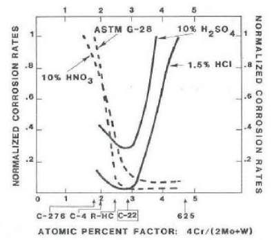
Figure 2.
Thermal stability as characterized by the resistance to intergranular corrosion in boiling 23% H2SO4 + 1.2% HCl + 1% FeCl3 + 1% CuCl2. The numbers under the circles indicate the corrosion rates in mils per year of samples tested after aging heat treatment at the corresponding time and temperature.
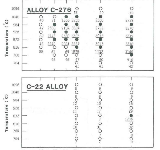
Figure 3.
Cyclic Polarization Curves with Hysteresis Loop in Aerated 3.5 wt. % NaCl + 0.1N Hcl: 10
a. 316L Stainless Steel
b. HASTELLOY® C-22® alloy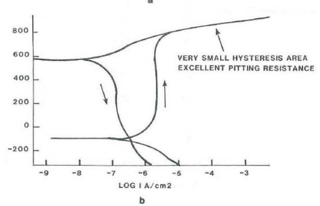
Figure 4.
Salt Fog/Acid Dip Corrosion Data. 20 Weeks/20 Acid Dips.
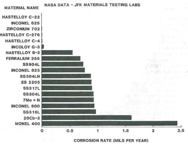
Figure 5.
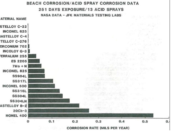
Figure 6.
Pitting observed on alloy C-276 0.004″ foil, following immersion testing in Green Death Solution:
a. General appearance with several perforations.
b. Cross-section of one perforation (200x).
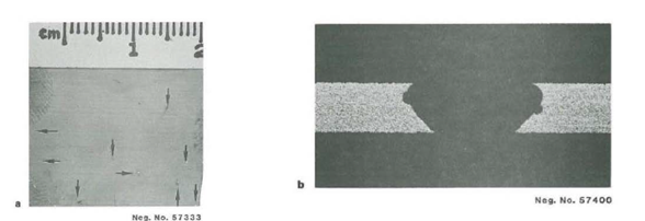
Figure 7.
Cross-section of As-Received 0.004″ foil (500x)
a. HASTELLOY alloy C-276
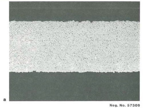
b. HASTELLOY alloy C-22®
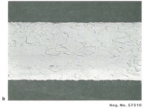
Figure 8.
Cavitation erosion behavior in distilled water a t room temperature
(Frequency 20 KHz, Amplitude 0.05 mm).
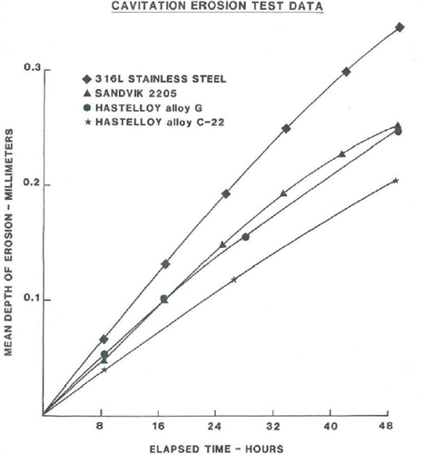
Figure 9.
317L Stainless Steel Base Metal
10% FeCl3 Solution; 35°C (95°F), 120-hour test
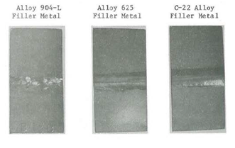
Figure 10.
Alloy 904—L Base Metal
10% FeCl3 Solution; 35°C (95°F), 120-hour test
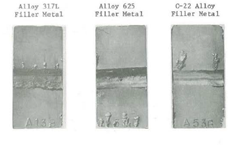
Figure 11.
HASTELLOY alloy G-3 Base Metal
4% NaCl + 0.1% Fe2(S04)3 + 0.O1M HC1 Solution; 65°C (149°F), 24-hour test

APPENDIX A
HASTELLOY® C-22® alloy bellows installed with the vacuum-jacketed cryogenic supply lines at the space shuttle launch site- John F. Kennedy Space Center.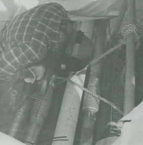

 en
en