General Haynes International Information
Back-purging and Welding Requirements for Fabrication of HASTELLOY® alloy Pipe Systems
Background
Periodically, fabricators are required to install piping systems where access to the inside of the pipe is not possible. In such situations, either open-butt pipe welding techniques or welding techniques using a consumable insert are employed. Because consumable inserts are not readily available for the HASTELLOY® alloy products, open-butt welding using the gas tungsten arc welding (GTAW) process is normally employed in making such root-pass welds.
When these one-sided welding techniques are used, it is necessary to protect the root side of the weld joint from oxidation during welding with an inert shielding gas (usually welding grade argon). The shielding technique, which protects the inside of the pipe, is called “back purging”.
Figure 1: Example of root weld made with poor back purging technique.
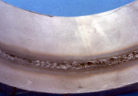
Lack of proper shielding produces a condition which is often referred to as “sugar” of the root pass. An example of such a root-pass weld, made on an 8″ diameter HASTELLOY® C-22® alloy pipe, is shown in Figure 1. An unacceptable root pass is characterized by a black, crusty appearance of the weld metal on the inside (root) of the pipe and an irregular root cross-section.
When this condition occurs, the molten weld metal does not flow out and “wet” the base material. This condition makes welding difficult and the passing of a radiographic examination nearly impossible. Common welding defects which form as a result of this condition include incomplete penetration, lack-of-fusion, root-pass cracking and root-pass suck back. It has been reported, by several Haynes International customers, that the nickel-base (HASTELLOY®) alloys are more difficult to weld, using this one-sided technique, than are the stainless or carbon steels.
Laboratory work was conducted to determine back purging and welding techniques which will produce acceptable open-butt root-pass welds in alloys such as HASTELLOY® C-22® alloy pipe. The following sections document the results of that laboratory work.
Back-purging Techniques
Two common methods are used to back purge a pipe root-pass weld zone. Purging the entire volume of a long pipe run is often suggested. Tables have been published concerning purge times for various pipe diameters and lengths of pipe run.(1) Local purging of the immediate volume around the weld zone is an alternative method of back purging and is generally the preferred technique. Various methods of forming the closure dams are reported in the literature. They include water soluble dams, inflatable bladder dams, collapsible disc dams and thermally disposable dams.(1,2,3) There are many companies which manufacture equipment and products to accomplish such a local purge. A partial list of suppliers of back-purging equipment is presented at the end of this report.
Back-purging is accomplished in two steps. First, the dams must be installed and the weld zone volume purged with argon to acceptable levels. Secondly, purging must continue and accompany the actual welding operations.
In the work reported in this document, *only water-soluble dams were used. As a way to ensure that the purge gas entered the enclosed weld zone with a minimum of gas-flow turbulence, thus allowing the shortest purge time,(5) a diffusing device was manufactured and secured at the bottom of one of the purge dams. The local weld zone was purged at about 40 cubic feet per hour (CFH) of gas-flow rate. Such flow rates allowed purging of an 8″ diameter pipe section to about 5000-ppm oxygen content in less than 5 minutes. Regardless of the length of time of purging after the initial 5 minutes, it was not possible to consistently obtain oxygen contents below the 5000-ppm oxygen level. The 5000-ppm oxygen level was, however, determined to be acceptable for welding the nickel-base alloys.
The welding literature(1,3,4) recommends that the back purge flow rates be low (“barely detectable at the gas exit port”) and makes no reference to the welding torch flow rates at all. In this work, it was determined that the selection of shielding gas flow rates for both the back purge and the welding torch are critical in the making of sound root-pass welds.
Specifically, it was determined that a ratio of approximately 4 to 1, between the back purge flow rate and the welding torch flow rate, is necessary to make a sound root-pass weld. The flow rates which are now recommended for welding HASTELLOY® alloy pipe are 40 CFH for the back-purge and 10 CFH for the welding torch. Figure 2 is included to show the criticality of those relative flow rates on actual root-pass welds.
*Patent bending
Figure 2: Actual root pass welding results.
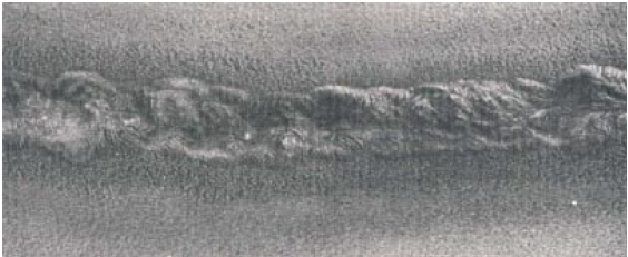
Unacceptable root weld
Flow rates: Back purge – 10 CFH, welding torch 30 CFH
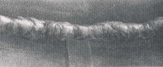
Acceptable root weld
Flow rates: Back purge – 40 CFH, welding torch 10 CFH
It should be noted that the weld zone volume was purged to the 5000-ppm oxygen level prior to the start of welding. The “acceptable” root-pass weld was made first. Then the flow rates were reversed and the “unacceptable” root-pass weld was made. This is an indication that the purity of the back purge gas was acceptable at the start of the “unacceptable” weld and that the difference in weld quality is a result of the flow rates only.
The selection of the flow rate (10 CFH) for the torch shielding gas is somewhat low based upon standard recommendations for welding the HASTELLOY® nickel-base alloys.(6) This low welding torch flow rate does not, however, affect the torch side shielding as indicated by bright, shiny beads which are present using either shielding technique.
Welding Techniques
The purging and welding of a piping joint generally involves six operations.
Those operations include:
1. Preparation of pipe ends
2. Installation of purge dams
3. Fit-up of pipe sections
4. Purge pipe weld zone
5. Tack weld pipe sections
6. Closure welding
1. Preparation of the pipe ends is considered a very important step in this welding operation. A diagram of a typical weld preparation detail is shown in Figure 3. It is recommended that a weld angle of about 35 degrees be machined onto the pipe ends.
Further, it is recommended that both the ID and OD be cleaned to bright, shiny metal for a distance of about 1″ from the weld preparation edge and that a land be machined or ground per the dimensions shown in Figure 3. After all machining and grinding operations are completed, thorough cleaning and degreasing of the entire area is required.
It should be recognized that the pipe will have some ovality which can make for a mismatch in the ID during fit-up and welding (see Figure 3), it may be necessary to counter-bore the ID of the pipe sections in order to obtain an acceptable match around the inside diameter of the pipe.
2. Any of the purging systems discussed above, except thermally disposable dams, are considered acceptable for HASTELLOY® alloy pipe systems. As a way to insure that the purge gas enters the enclosed weld zone with a minimum of gas flow turbulence, a gas diffusing device is recommended. Figure 4 shows one possible design, for use with large diameter pipes, which can be fabricated in the field. Modifications to such a general design will certainly be required to meet other specific job requirements. The purge dams must be installed deep enough in the pipe section so that the heat of welding will not cause damage to the dams.
3. Fit-up of the pipe sections requires care so as to establish proper root-gap tolerance between the two pipe sections. It is generally recommended that the root gap be at least 1/32″ larger than the diameter of welding filler wire to be used. This will allow for manipulation of the filler wire even when some shrinkage occurs during tack welding and closure welding.
4. Purging of the weld zone is done at about 40 CFH. The weld joint should be sealed around the circumference of the pipe except for a small opening at the top position of the pipe. The intention is to have the shielding gas enter at the bottom of the weld zone and exit at the top. If pipe welding is being performed in the vertical (2G) position, the gas should enter at the bottom purge dam and exit through a small hole in the top purge dam. Normally, flow rates and times are selected so that a minimum of 5 to 6 shielding gas volume changes take place prior to welding.(1)
5. Tack welding is necessary to ensure that the two pipe sections do not move during subsequent closure welding. The tack welds must be large enough and placed often enough around the joint circumference so that the root gap remains open and wider than the welding filler wire diameter. Generally, the weld joint is kept sealed except in the area were welding is being conducted.
It is recommended that the tack welds be ground to a feather edge. This will help ensure that the closure welds will tie into the tack welds and not leave small defects which might be detected during radiographic examination. The shielding gas flow rates used during tack welding, and during subsequent closure welding, should be about 40 CFH for the back purge and about 10 CFH for the welding torch. Other welding parameters are documented in Table 1.
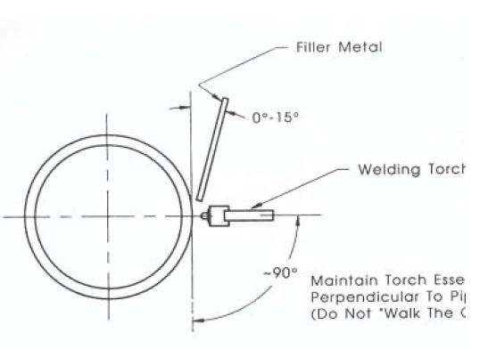
Torch position and filler wire position are critical to the success of root-pass welding. A diagram showing the positions of the GTAW torch body and welding filler wire relative to the pipe are shown in Figure 5.(1) Torch and filler wire manipulation consist of torch movement from sidewall to sidewall which forms a “keyhole”. Two drops of filler material are melted into each sidewall with each back and forth motion of the welding torch. The filler metal is generally positioned in the root-gap opening. If the root gap “closes-up”, not allowing the filler wire to be placed in the root-gap opening, the amount of weld reinforcement at the root will be limited.
6. The closure welding is performed much like the tack welding. Again, the joint is kept sealed except in the area were welding is being performed. During the last portion of the closure weld, the gas purge flow rate may have to be lowered so that the dams will not be damaged due to purge gas pressure increase. It is generally recommended that back purge gas be maintained for the first two fill pass welds. This will help ensure that the root pass is not heavily oxidized during these subsequent weld passes.
The selection of welding process for the fill passes is left up to the discretion of the field welding engineer.
References
- “Recommended Practices for Root Pass Welding of Pipe Without Backing”,
ANSI/AWS D10.11-87, published by the American Welding Society, Miami, FL
33135. - “Purging Practice for Nuclear Pipe Welding”, Eric Holby, Welding Engineer,
January, 1973. - “Power-plant pipe must be leak-free”, Eric R. Holby, Welding Design &
Fabrication, March 1986. - “Recommended Practices for Welding Austenitic Chromium-Nickel Stainless
Steel Piping and Tubing”, AWS D10.4-79, published by the American Welding
Society, Miami, FL 33135. - ASM Handbook Volume 6, Welding and Brazing, 9th Edition, page 199,
published by ASM International, Metals Park, OH 44073 - Fabrication of HASTELLOY® Corrosion-Resistant Alloys, H-2010C, page 11,
published by Haynes International, Inc., Kokomo, IN 46902
Partial List of Suppliers
- Dissolvo Products, Gilbreth International Corporation, 3300 State Road,
PO Box 779, Bensalem, PA 19020 - Emerson Hallenbeck Cone Purge Unit Company, 2934 Shoreland Avenue,
Toledo, OH 43611 - Sloan Purge Products, Inc., 3112 Antonino Avenue, Bakersfield, CA 93308
- Safety Main Stopper Co., Inc., PO Box 170287, Times Plaza Station, Brooklyn,
NY 11217
Table 1
Suggested Welding Parameters for Root-Pass Open-Butt Gas Tungsten Arc Welding (GTAW) of Pipe
Base material thickness:
Filler material diameter:
Interpass temperature:
up to 1/2″
3/32″ (1/8″ diameter can be used with modification to the root gap dimension)
200°F maximum
Flow rate 10 CFH
Flow rate 40 CFH
Amperage: 50 – 125 amps
Voltage: 11 – 12 volts
Travel speed: 2 – 4 inch per minute
Feather grind all starts and stops (both tack welds and closure welds)
Figure 3: Suggested Weld Angle Preparation and Fit-up.
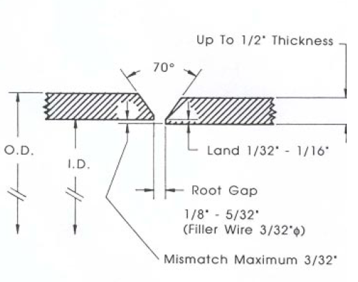
Figure 4: Example of Diffuser Device Capable of Being Manufactured in the Field.
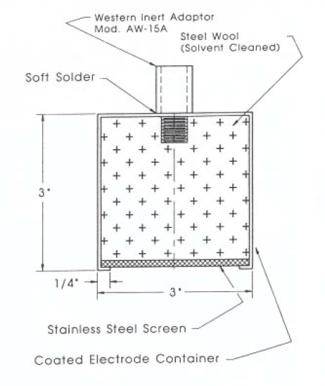
Figure 5: Suggested Welding Torch and Filler Wire Placement.